

Computer Aids for VLSI Design
Steven M. Rubin
Copyright © 1994
|
Appendix 4 of 7 | |
The Electronic Design Interchange Format (EDIF) is a recent effort at capturing all aspects of VLSI design in a single representation. This is useful not only as a communications medium to manufacturing equipment, but also as an interchange format between CAD systems, since none of the high-level information is lost. EDIF is designed to be both easy to read by humans and easy to parse by machines.
EDIF files resemble the LISP programming language because of the use of prefix notation enclosed in parentheses. For example, the CIF polygon:
P 100 100 150 200 200 100;
looks like this in EDIF:
 (polygon (point 100 100)
          (point 150 200)
          (point 200 100))
All EDIF statements consist of an open parenthesis, a keyword, some parameters, and a close parenthesis. The parameters can be other statements, which is what gives EDIF structure. Actually, an EDIF file contains only one statement:
(edif parameters)
where parameters are the described circuit.
Not only does EDIF resemble LISP, but in its highest level it contains all of LISP and is an extension of this highly expressive language. However, in the interest of making parsing simple, there are three levels of EDIF, and lower levels are less powerful. Level 1, the intermediate level, allows variables to be used and cell definitions to be parameterized. EDIF level 0 has no programmability and requires constants in all statements. A LISP preprocessor can translate from EDIF levels 1 or 2 down to level 0, and any given level of EDIF can be read by a parser of a higher level. Since level 0 is all that is necessary for most interchange and all manufacturing specification, only that level will be discussed here. Also, some of the EDIF constructs that deal with simulation, routing, behavior, and other unusual specifications will not be covered in detail.
An EDIF file contains a set of libraries, each containing a set of cells. Each cell can be described with one or more views that show the cell in the form of a schematic, layout, behavioral specification, document, and more. Each view has both an interface and a contents so that it is cleanly defined and can be linked to other views with a view map. Libraries may also contain technology information so that defaults can be given for behavior, graphics, and other attributes. The overall structure of an EDIF file looks like this:
 (edif name
   (status information)
   (design where-to-find-them)
   (external reference-libraries)
   (library name
     (technology defaults)
     (cell name
       (viewmap map)
       (view type name
         (interface external)
         (contents internal)
       )
     )
   )
 )
The status statement is used to track design progress and contains
author names, modification dates, and program versions.
Additional status statements may appear in each library, cell, and view.
The design statement indicates where a completed design may be
found by pointing to the top cell of a hierarchical description.
The external statement names libraries that will be used but are
not listed in this EDIF file.
The library, cell, and view blocks can be repeated as
necessary.
There is also a comment statement that can be placed at the end of most
blocks to add readability to the file.
Here is an example of an EDIF file that further illustrates
the outer level:
 (edif my-design
   (status
     (edifversion 1 0 0)
     (ediflevel 0)
     (written
       (timestamp 1985 4 1 11 16 6)
       (accounting author "Steven Rubin")
       (accounting location "Palo Alto")
       (accounting program "Electric")
       (comment "timestamp contains")
       (comment " year, month, day,")
       (comment " hour, minute, and second")
     )
   )
   (design hot-dog-chip
     (qualify hot-dog-library top-cell)
     (comment "find top-cell in hot-dog-lib")
   )
   (external pad-library pla-library)
   (library hot-dog-library
     (technology 3-micron-nMOS
       ...
     )
     (cell top-cell
       (viewmap ... )
       (view masklayout real-geometry
         (interface ... )
         (contents ... )
       )
       (view schematic more-abstract
         (interface ... )
         (contents ... )
       )
     )
   )
 )
The written part of a status block may be repeated to
show all authors and update events.
Also note that the qualify statement, which names a cell in a particular
library, is generally useful and can appear anywhere that an isolated
name may be ambiguous or undefined.
In the following sections, more information is given to describe the
contents, interface, viewmap, and technology blocks.
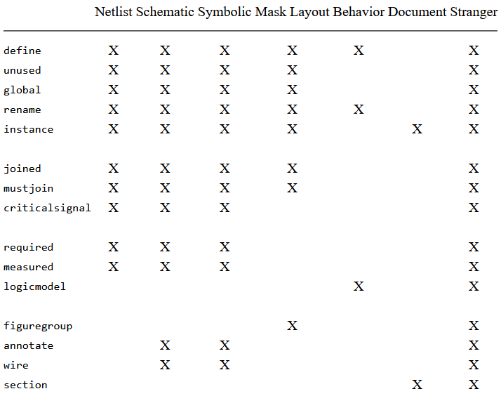
The contents of a cell may be represented in a number of different ways depending on the type of data. Each representation is a different view, and multiple views can be used to define a circuit fully. EDIF accepts seven different view types: netlist for pure topology as is required by simulators, schematic for connected logic symbols, symbolic for more abstract connection designs, mask layout for the geometry of chip and board fabrication, behavior for functional description, document for general textual description, and stranger for any information that cannot fit into the other six view types.
The statements allowed in the contents section vary with the view type
(see Fig. D.1).
The netlist, schematic, and symbolic views are essentially the same because
they describe circuit topology.
The allowable statements in these views are the declarations define,
unused, global, rename, and instance; the
routing specifications joined, mustjoin, and criticalsignal;
and the timing specifications required and measured.
Schematic and symbolic views also allow the annotate and wire
statements.
The mask-layout view allows all of the declarations, some of the
routing constructs, and the figuregroup statement for actual graphics.
The behavior view allows only a few declarations and the
logicmodel statement.
The document view allows only the instance and section
constructs.
Finally, the stranger view allows everything but supports nothing.
It should be avoided whenever possible.
Declarations establish the objects in a cell including signals, parts, and names. Internal signals are defined with the statement:
(define direction type names)
where direction is one of input, output, inout,
local, or unspecified.
Only local and unspecified signals have meaning in the contents
section of a view; the others are used when this statement appears in an
interface section.
The type of the declaration can be port, signal,
or figuregroup,
where port is for the interface section, signal is for the contents
section, and figuregroup is for the technology section of a library.
The names being declared can be given as a single name or as a list
of names aggregated with the multiple clause.
In addition to all these declaration options, it is possible to define
arrays by having any name be the construct:
(arraydefinition name dimensions)
These arrays can be indexed by using the construct:
(member name indexes)
Here are some examples of the define statement:
 (define input port Clk)
 (define unspecified signal (multiple a b c))
 (define local signal
   (arraydefinition i-memory 10 32))
After the declaration of signals, a number of other
declarations can be made.
The unused statement has the form:
(unused name)
and indicates that the defined name is not used in this cell view and should
be allowed
to pass any analysis that might find it to be an error.
The global declaration has the form:
(global names)
and defines signals to be used inside the cell view and one level lower, in subcomponents that are placed inside the view. Where these subcomponents have ports that match globally declared names, they will be implicitly equated.
Yet another declaration is rename, which can associate any EDIF
name with an arbitrary string.
This allows illegal EDIF naming conventions to be used, such as in this
example:
(rename bwest "B-west{ss}")
Hierarchy is achieved by declaring an instance of a cell in the contents
of another cell.
The format of the instance statement is as follows:
(instance cell view name transform)
The name of the other cell is in cell and the particular view to use is in view. This allows the hierarchy to mix view types where it makes sense. A local name is given to this instance in name and an optional transformation is specified in transform, which looks like this:
(transform scale rotate translate)
where scale can be:
(scalex numerator denominator)
or:
(scaley numerator denominator)
translate has the form:
(translate x y)
and rotate can be either:
(rotation counterclockwise-angle)
or:
(orientation manhattan-orientation)
where manhattan-orientation is one of R0, R90, R180, R270,
MX, MY, MYR90, or MXR90.
So, for example, the expression:
(transform (scalex 3 10) MX (translate 5 15))
will scale the instance to three-tenths of its size, mirror it about the x
axis (negate the y coordinate) and then translate it by 5 in x
and 15 in y.
Although any of the three transformation elements can be omitted, when present
they must be given in the order shown, and are applied in that sequence.
Unfortunately, versions of EDIF before 3.0 have no provision for non-Manhattan orientation
because the rotation clause did not exist before then.
Arrays of instances can be described by including a step
function in the translate part of the transform clause.
This will indicate a series of translated locations for the instances.
The format of this iteration is:
(step origin count increment)
So, for example, the clause:
(step 7 3 5)
will place three instances translated by 7, 12, and 17 in whichever coordinate
this appears.
The rotation and scale factors will apply to every array element.
Also, it is possible to use different instances in each array location
by mentioning multiple cell names in the instance clause.
For example,
 (instance (multiple carry add)
   more-abstract add-chain
   (transform (translate 0 (step 0 16 10)))
 )
will create an array of 16 instances stacked vertically that alternate between the "more-abstract" view of the "carry" cell and the "more-abstract" view of the "add" cell. This entire instance will be called "add-chain."
To indicate connectivity, the joined construct
identifies signals or ports that are connected.
The mustjoin construct indicates that signals do not yet connect but
should when routing takes place, and the criticalsignal construct
establishes priorities for the routing.
To illustrate further EDIF's expressive power in routing specification,
there is a weakjoined construct that defines a set of joins,
only one of which must be connected, and a permutable statement
that declares sets of connection points to be interchangeable.
These last two statements are found only in the interface section; however,
none of the routing constructs will be described in detail.
The final set of constructs in the netlist, schematic, and symbolic views are those concerned with timing. As an example of the level of specification available, the statement:
 (required (delay (transition H L
   (minomax 10 20 30)) here there))
states that the required delay of a high-to-low transition between points
"here" and "there" is between 10 and 30, with a nominal value of 20.
The measured statement can be used in the same way to document
actual timing.
The logicmodel statement, found only in the behavior view, allows
a detailed set of logic states and conditions that can control simulation
and verification.
The EDIF specification should be consulted for full details of these
timing, behavior, and routing constructs.
In the mask-layout view, geometry can be specified with
the figuregroup construct, which looks like this:
 (figuregroup groupname
   pathtype width color
   fillpattern borderpattern
   signals figures)
where the groupname refers to a figuregroupdefault clause
in the technology section of this library (described later).
This set of defaults is available so that the graphic characteristics
pathtype, width, color, fillpattern, and
borderpattern
need not be explicitly mentioned in each figuregroup statement.
These five graphic characteristics are therefore optional and have the
following format:
 (pathtype endtype cornertype)
 (width distance)
 (color red green blue)
 (fillpattern width height pattern)
 (borderpattern length pattern)
The pathtype describes how wire ends and corners will be drawn
(either extend, truncate, or round).
The width clause takes a single integer to be used as the width of
the wire.
The color clause takes three integers in the range of 0 to 100, which
give intensity of red, green, and blue.
The fillpattern clause gives a raster pattern that will be tessellated
inside of the figure.
Two integers specify the size of the pattern and a string of zeros and ones
define the pattern.
Finally, the borderpattern describes an edge texture by specifying a single
integer for a pattern length followed by a pattern string that is repeated
around the border of the figure.
Here are examples of these figuregroup attributes:
 (pathtype round round)
 (width 200)
 (color 0 0 100)
 (fillpattern 4 4 "1010010110100101")
 (borderpattern 2 "10")
Inside of a figuregroup statement, the
actual geometry can be specified directly with the figures constructs
or can be aggregated by signal with the signals construct, which has
the form:
(signalgroup name figures)
The figures construct in a figuregroup can be
either polygon, shape, arc, rectangle, circle,
path, dot, or annotate.
The polygon is of the form:
(polygon points)
where each point has the form:
(point x y)
A shape is the same as a polygon except that it can contain
point or arc information, freely mixed.
The arc has the form:
(arc start middle end)
where these three points are the start point, any point along the arc,
and the endpoint.
The rectangle takes two points that are diagonally opposite each
other and define a rectangle.
A circle takes two points that are on opposite sides and
therefore separated by the diameter.
The path takes a set of points and uses the width and
pathtype information to describe the geometry further.
The dot construct takes a single point and draws it in a
dimensionless way (it should not be used in actual fabrication
specifications).
In schematic and symbolic views, the annotate clause may be used
to add text to a drawing.
The form:
(annotate text corner1 corner2 justify)
will place text in the box defined by the two diagonally opposite
corners, and justify the text according to one of nine options:
upperleft, uppercenter, upperright,
centerleft, centercenter, centerright,
lowerleft, lowercenter, or lowerright.
For example:
 (annotate "probe here"
   (point 50 50) (point 200 100) uppercenter)
will place the string "probe here" in the upper part of the box
50 ![]() x
x ![]() 200 and
50
200 and
50 ![]() y
y ![]() 100, centered.
100, centered.
Another construct allowed only in schematic and symbolic views is wire.
This connects two ports with a wire that can be described graphically.
For example:
 (wire clock.in gated.timer
   (figuregroup metal
     (path (point 10 15)
	       (point 20 15)
		   (point 20 25))
   )
 )
connects the two points on the metal layer.
The last contents statement to be mentioned is the section
construct, which is found only in document views and can hierarchically
describe chapters, sections, subsections, and so on.
For example:
 (section "Chapter 1"
   (section "Introduction"
     "This is a book about VLSI CAD tools."
     "I hope you like it."
   )
 )
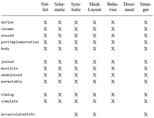
In addition to there being seven different ways of specifying the contents of a cell, there are the same seven views that apply to the interface of a cell. The interface section is the specification of how a cell interacts with its environment when used in a supercell.
Unlike the contents views, the seven interface
views are all essentially the same (see Fig. D.2).
The netlist, schematic, symbolic, mask layout, behavior, and stranger views
can all contain the same declarations: define, rename,
unused, portimplementation, and body.
They also allow the routing statements joined, mustjoin,
weakjoined, and permutable, in addition to the simulation
statements timing and simulate.
The symbolic, mask-layout, and stranger views add the arrayrelatedinfo
construct, which enables gate-array specification to be handled.
The document view offers no constructs as this text rightly belongs in the
contents section.
The first interface statement to be discussed is portimplementation,
which describes the ports and their associated components, graphics, timing,
and other properties.
Although ports can be declared with the define statement,
portimplementation allows more information to be included
in the declaration.
The format is:
 (portimplementation portname figuregroups
   instances properties)
where the portname is the name of the port as it will be used in
supercells.
The figuregroups describe any graphics attached to the port, the
instances specify any subcells that describe the port, and
the properties may indicate power-consumption ratings.
Ports that are further described by instances of other cells
do not need figuregroups to define them, so much of the
portimplementation statement is optional.
The body statement is used to describe the external or interfaced
aspect of a cell.
In mask-layout views, this can describe a protection frame for
design-rule checking and compaction.
In other views it is simply used to give an external appearance to
instances of the cell.
The format is:
(body figuregroups instances)
where instances are subcells that can be used to describe the body.
The arrayrelatedinfo statement, which
is used in gate-array specification, is allowed only in symbolic,
mask-layout, and stranger views.
This can be used to declare the background array:
(arrayrelatedinfo basearray (socket info))
or the individual cells:
(arrayrelatedinfo arraysite (plug info))
or macros of cells:
(arrayrelatedinfo arraymacro (plug info))
These statements define a grid that can be connected in a rigid manner, specified by the plugs and sockets. Sockets define permissible connection options and plugs make these connections to give precise gate-array interface. Consult the EDIF document for more information.
The final interface section constructs, which will not be described in
detail, are timing and simulate.
The timing statement gives port delays for various transitions, and
gives stability requirements for the signal values.
The simulate statement lists test data and expected results.
To relate different views, a viewmap section can exist in each cell,
which associates ports from different
interface sections or instances from different contents sections.
Port mapping is done with:
(portmap ports)
where the list of ports is of the form:
(qualify viewname portname)
Thus to equate port C of the mask-layout view with port D of the schematic view, the map would look like this:
 (viewmap
   (portmap
     (qualify real-geometry C)
     (qualify more-abstract D)
   )
 )
Note that the viewname is the declared name given to the view.
To relate instances of a cell in different views, the same format applies except that a many-to-one mapping is allowed. For example,
 (instancemap
   (qualify real-geometry pullup pulldown)
   (qualify more-abstract inverter)
 )
will map both the pullup and the pulldown in the mask-layout view to the inverter in the schematic view.
The technology section provides a background of information for the
description of a library.
Defaults can be set for other statements in the library,
such as the figuregroup.
Also, the real units of distance, time, power, and so on can be established.
The technology section has the following format:
 (technology name
   defines renames
   figuregroupdefaults
   numberdefinitions gridmaps
   simulation
 )
where name is an identifier for this technology.
A set of define statements can be used to declare default figuregroups
for various signal types and rename statements can be used to establish
name bindings in the library.
The figuregroupdefault statement takes a name and a list of
pathtype, width, color, fillpattern, and
borderpattern constructs to establish the defaults for
subsequent figuregroup statements in the library.
The numberdefinition statement is important because it
sets the scale of all EDIF units as follows:
 (numberdefinition SI
   (scale distance edif real)
   (scale time edif real)
   (scale capacitance edif real)
   (scale current edif real)
   (scale resistance edif real)
   (scale voltage edif real)
   (scale temperature edif real)
 )
The name SI is a standard that should always appear unless an alternate
set of unit values is being declared.
Any of the scale clauses may be used to declare the number of
units in the EDIF file that correspond with real units.
Real units for distance are in meters, which means that the clause:
(scale distance 1000000 1)
causes one million EDIF units to be a meter (or one EDIF unit to be a micron). The real-time unit is the second, capacitance is in farads, current is in amperes, resistance is in ohms, voltage is in volts, and temperature is in degrees celsius.
The gridmap clause of the technology section can be used to
declare nonuniform scaling in the x and y axes.
For example,
(gridmap 3 4)
will set the x units to be three times the numberdefinition
distance and the y coordinates to be four times that amount.
This nonuniform scaling of all coordinates has limited application.
A final use of the technology section is for simulation defaults. As with all other simulation constructs, these will not be discussed here.
|
Prev |  |
TOC | Next | |
 |